Semi-Automated Bearing Diagnostics – Three Case Studies
N. Sawalhi and R.B. RandallSchool of Mechanical and Manufacturing Engineering,
The University of New South Wales,
Sydney 2052, Australia
Email: b.randall@unsw.edu.au
Published:
Abstract
Most commercial vibration data loggers and analyzers are using diagnostic technology developed twenty years ago. Many new developments in applied signal processing have occurred since that time, and could easily be incorporated into such analyzers. A number of techniques found invaluable for rolling element bearing diagnostics are illustrated through three case histories on very different machines, a very high speed bearing test rig, a planet bearing fault in a helicopter gearbox, and the main bearing of a very low speed radar tower. A primary technique (discrete-random separation) separates bearing from gear signals (and any other discrete frequencies), since the latter quite often dominate, even when in good condition.
Another technique (spectral kurtosis) gives an indication of which frequency bands are dominated by bearing fault signals, and thus what frequency band to demodulate for optimum envelope analysis. This technique only works when the impulses from the bearing faults are well separated, and this is not always the case for very high speed machines. A further technique (minimum entropy de-convolution) sharpens up the impulses so that they become separated and give much earlier fault indications. The separation of the impulses from entry into and exit from faults such as spalls, made possible by this technique, gives information about the size of the fault, whose evolution with time can thus be used prognostically. The three case histories illustrate the semi-automatic application of these techniques in very different situations. Only very minor user interaction is required, to define frequency ranges of interest, basic diagnostic parameters etc. The results show clear diagnosis, and valuable trending of parameters, in situations with a great deal of background noise and masking.
Introduction
Rolling element bearings are a component of most machines, from the very fast, eg gas turbines, to the very slow, eg slew bearings in mining equipment. Vibration analysis can be applied very effectively to their condition monitoring in all three aspects (detection, diagnosis, prognosis), but current monitoring equipment, for either permanent or intermittent monitoring, does not make use of many techniques which have been developed in recent years, and which now allow a semi-automated approach, even for bearings covering a wide range of machine speeds, loads and applications. This paper demonstrates this by applying a standardized approach to the signals from three widely different machines. The first is a helicopter gearbox, characterized by having a wide range of shaft speeds internally, many different bearings on different shafts, as well as strong vibration signals from the large number of different gears, including a planetary gear set. The signals from the planet bearings, for example, have to travel via a tortuous, time-varying path to external acceleration transducers. The second is a high speed bearing used in a gas turbine, but in this case mounted in a bearing test rig. A characteristic of the signals from high speed bearings is that the individual impulse responses, from impacts with the faults, tend to overlap and not give a clear series of pulses as normally required for the envelope analysis method used to diagnose them. The third case is from the support bearing of a rotating radar tower, and thus with extremely low speed. The tower makes one revolution in 12 s.
VIBRATION SIGNALS FROM FAULTY BEARINGS
Vibration signals from localized faults in rolling element bearings consist of a series of impulse responses from the impacts on the faults by the mating elements. These typically excite a wide range of resonance frequencies up to tens of kHz (lower for larger machines). The repetition frequencies (as a multiple of shaft speed) are characteristic of the fault location (eg outer race, inner race, rolling element), but the formulas for the characteristic frequencies are the kinematic frequencies assuming no slip. However, they contain a factor cos, which is the angle of the load from the radial, and this means that there is always some slip, because can only be defined on the average, and the ratio of radial to axial load varies for each rolling element as it rotates. Some rolling elements are trying to rotate faster than others, but the cage keeps the mean frequency constant (though different from the kinematic value), while permitting a small random variation in the spacing of the rolling elements (and thus in their impact frequencies).
The excited impulse responses, in particular in terms of acceleration, which is the most commonly measured parameter, are dominated by the resonance frequencies, and a simple frequency analysis of the raw signal contains almost no additive component at the low harmonics of the bearing frequencies. As shown in Ho and Randall (2000), they usually contain little diagnostic information at the higher resonance frequencies either, because of the random period variation which causes smearing of the higher harmonics. It has recently been postulated that the bearing signals can be modeled as cyclo-stationary, although the original cyclo-stationary model of Randall et al (2001) was later modified in [Antoni and Randall (2002), Antoni and Randall (2003)] to be "pseudo-cyclostationary" because true cyclo-stationary signals require the statistics to be (quasi-) periodic, not just approximately so, as in the case of bearings.
![]()

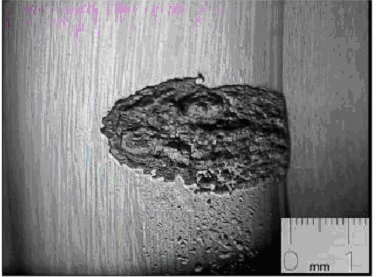
Fig 1: Early spall in the inner race

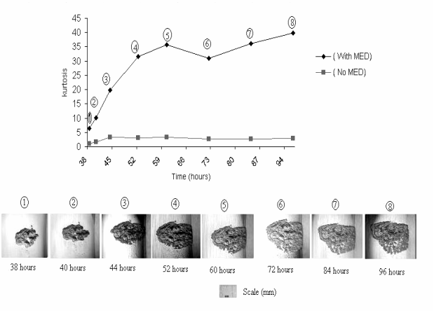
Fig 2: The development of kurtosis with and without MED, compared against fault size


