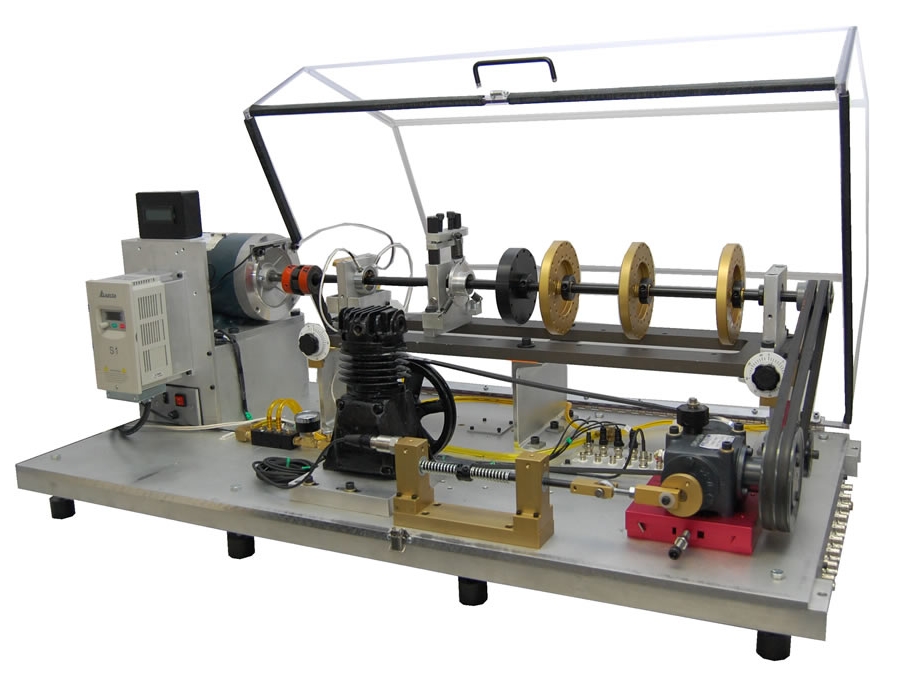
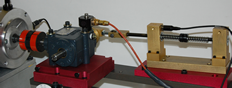
The MFS-Magnum provides a basic setup for performing experiments and learning vibration signatures of different machine malfunctions. However, a detailed investigation of particular and more advance vibration phenomena or machinery fault will require additional attachments and fixtures which are available through our optional kits.
|
Training Curriculum Manual (SQI-TRCM) |
- The training curriculum manual begins with textbook and basic classroom training in the fundamentals of classic machinery vibration, transducers, monitoring, signal processing, analysis, etc; from beginner to upper intermediate levels. It is both hands-on and mathematically oriented, being appropriate for both technicians and engineers.
- A wide array of laboratory exercises to be conducted on the MFS to provide a truly experiential learning environment.
- Use as a basis for accelerated course preparation and the development of vibration training program.
|  |
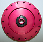
Eccentric Rotor (Requires MR-SCK-3/4) (M-ER-3/4) |
- Learn the effects of rotor eccentricity on vibration spectra.
- Determine relationships between eccentricity and unbalance.
- Develop techniques to locate and correct the effects of eccentricity.
- Learn the effect of varying the mass moment of inertia on vibration amplitude.
- The kit consists of one aluminum rotor with an asymmetrically located center and one clamp collar.
|  |
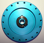
Cocked Rotor (Requires MR-SCK-3/4) (M-CR-3/4) |
- Learn the effects of a sheave that has not been fitted to the shaft properly.
- Learn vibration signature of a cocked rotor.
- Develop methods to correct cocked rotor problems.
- Learn the effect of varying the mass moment of inertia on vibration amplitude.
- The kit consists of a cocked aluminum rotor (0.5 degree off-axis) and one clamp collar.
|  |
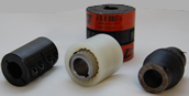
Coupling Type Set (Requires MR-SCK-3/4) (M-CK-3/4) |
- Learn the effects of coupling stiffness on rotor dynamics and vibration signature.
- Clarify the complexities of machinery shaft misalignment problems (spectral pattern for shaft misalignment is a strong function of coupling stiffness).
- The kit consists of one gear, one LoveJoy, one rubber, and one rigid steel coupling.
- Learn the effect of varying the mass moment of inertia on vibration amplitude.
- The kit consists of a cocked aluminum rotor (0.5 degree off-axis) and one clamp collar.
|  |
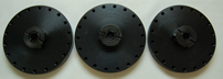
Centrally Bent Rotor Shaft for Balance Studies (MG-BRS-3/4) |
- Demonstrate the signature of a bent shaft.
- Observe the difficulty associated with attempting to balance a rotor mounted on a bent shaft.
- Learn to cope with the alignment issues due to a bent shaft.
- The kit consists of one 3/4″ shaft centrally bent ~0.020″
- The kit consists of a cocked aluminum rotor (0.5 degree off-axis) and one clamp collar.
| |
Coupling-End Bent Rotor Shaft for Balance Studies (MG-CBRS-3/4) |
- Investigate complicated vibration signature due to gyroscopic effects.
- Observe the difficulty associated with attempting to balance an overhung rotor on a bent shaft.
- Learn to cope with the alignment issues due to a bent shaft.
- The kit consists of one 3/4″ shaft coupling-end bent ~0.010″
- The kit consists of a cocked aluminum rotor (0.5 degree off-axis) and one clamp collar.
| |
Rolling Bearing Resonance/Critical Study Kit (MG-RSK-1/2) |
- Study resonance and critical speed phenomena, at speeds below 2000 RPM to simulate real world operating conditions while improving safety. The standard 3/4″ shaft has a high resonance frequency, 7000 RPM or more depending on rotor positions.
- Study damaging effects of resonance and develop control methods.
- Relocate rotors and supports to study the effects of mass and stiffness on resonance frequencies and mode shapes.
- Study beating due to closely spaced modes.
- Study non-linear dynamics for chaos modeling.
- The kit consists of one 1/2 “shaft, three rotors, two rolling element bearings, and one coupling.
|  |
Higher Resonance Study Kit (M-RDK-1/2) |
- Study rolling element bearings on the MFS-RDS.
- The kit consists of three steel disks.
- Relocate rotors and supports to study the effects of mass and stiffness on resonance frequencies and mode shapes.
- Study beating due to closely spaced modes.
- Study non-linear dynamics for chaos modeling.
- The kit consists of one 1/2 “shaft, three rotors, two rolling element bearings, and one coupling.
|  |
Sleeve Bearing Resonance Study Kit (M-SBK-1/2) |
- Study resonance and critical speed phenomena in sleeve bearings.
- The kit consists of two customized grease-lubricated, babbitt lined sleeve bearings, two bearing pedestals, and various thickness plastic shims
- Requires M-RSK-1/2
- Study beating due to closely spaced modes.
- Study non-linear dynamics for chaos modeling.
- The kit consists of one 1/2 “shaft, three rotors, two rolling element bearings, and one coupling.
|  |
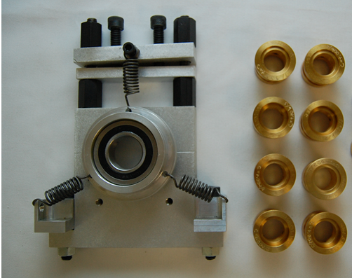
Oil whirl/whip in-depth study kit for 3/4″ shaft (MG-OWSK-3/4) |
- Study the effect of stiffer rotor on oil induced instability and understand whirl/whip phenomena and how to avoid it. The idea is to understand and control the whirl/whip phenomena. 3/4″ shaft provides not only stiffer rotor but also lighter balance, eccentric and cocked disks for more investigation to enhance the understanding.
- The kit consists total of four sleeve bearing pairs to give bearing clearances of 6 mils (0.001′) for two different lengths(2 pairs) & 2 mils for one length (1 pair) ,and elliptical bearings (1 pair) to avoid whirl/whip instability, and one shaft centering device.
- Requires M-RSK-1/2
- Study beating due to closely spaced modes.
- Study non-linear dynamics for chaos modeling.
- The kit consists of one 1/2 “shaft, three rotors, two rolling element bearings, and one coupling.
|  |
Oil whirl/whip in-depth study kit for 1/2″ shaft (M-OWSK-1/2) |
- Study effects of bearing clearance, L/D ratio, and rotor loading effects on oil induced instability, and to understand whirl/whip phenomena and how to avoid it.
- The kit consists total of five sleeve bearing pairs to give bearing clearances of 2 and 6 mils (0.001′) for two different lengths(4 pairs) and elliptical bearings (1 pair) to avoid whirl/whip instability, and one shaft centering device insert.
- Requires MG-RSK-1/2, MG-OWSK-3/4
- Study beating due to closely spaced modes.
- Study non-linear dynamics for chaos modeling.
- The kit consists of one 1/2 “shaft, three rotors, two rolling element bearings, and one coupling.
|  |
3/4″ Shaft Sleeve Bearing (grease lubricated) kit (M-SBK-3/4) |
- Investigate waveform and spectral recognition of worn or loose fitting bearings.
- Modify the clearance of the split bearings with plastic shims.
- Perform shaft orbital analysis.
- The kit consists of two customized grease-lubricated, babbitt lined sleeve bearings, two bearing pedestals, and various thickness plastic shims.
- Study non-linear dynamics for chaos modeling.
- The kit consists of one 1/2 “shaft, three rotors, two rolling element bearings, and one coupling.
| |
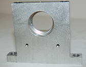
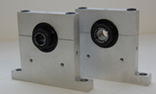
Cocked Bearing Housing (M-CBM-3/4) |
- Recognize the signature of a cocked bearing due to improper seating or due to inconsistent installation.
- The kit consists of one cocked bearing housing.
- Perform shaft orbital analysis.
- The kit consists of two customized grease-lubricated, babbitt lined sleeve bearings, two bearing pedestals, and various thickness plastic shims.
- Study non-linear dynamics for chaos modeling.
- The kit consists of one 1/2 “shaft, three rotors, two rolling element bearings, and one coupling.
|  |
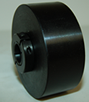
3/4″ shaft bearing loader (Requires MR-SCK -3/4) (M-BL-3/4) |
- Investigate bearing radial loading effects.
- Enhance the spectral amplitude of system.
- The kit consists of one 3/4″ bore loader weighting 11lb (5kg) and two clamp collars.
- The kit consists of two customized grease-lubricated, babbitt lined sleeve bearings, two bearing pedestals, and various thickness plastic shims.
- Study non-linear dynamics for chaos modeling.
- The kit consists of one 1/2 “shaft, three rotors, two rolling element bearings, and one coupling.
|  |
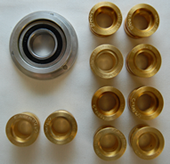
3/4″ Bearing Fault Kit (Requires MR-SCK -3/4) (M-BFK-3/4) |
- Learn waveform and spectra of classic bearing defects.
- Learn about signal processing issues such as averaging techniques, leakage, and spectral resolution on determining bearing faults.
- Perform experiments with increasing severity of defects.
- Determine why an ultra-high resolution spectrum is needed to diagnose a bearing fault when fault frequencies are located close to multiples rotational speed.
- Learn how a large signal can mask adjoining low amplitude signal due to spectra leakage.
- The kit consists of one inner race defect, one outer race defect, one with ball defect, and one combination of defects.
|  |
1″ Shaft Bearing Study Kit (Requires M-BSK-1) (MG-BSK-1) |
- Study bearing fault frequencies away from multiples rotational speed. The standard 3/4″ shaft exhibit fault frequencies close to multiples rotational speed, requiring ultra high resolution spectra to clearly identify bearing fault frequencies.
- Identify bearing fault frequencies in the presence of defects at multiples of shaft speed without using high-resolution spectra.
- Understand the signal processing issues such as averaging, spectral resolution, and leakage phenomena.
- The kit consists of two split bearing housings, two 1″ inside diameter bearings, one 1″ diameter shaft, and one coupling.
- Learn how a large signal can mask adjoining low amplitude signal due to spectra leakage.
- The kit consists of one inner race defect, one outer race defect, one with ball defect, and one combination of defects.
|  |
1″ shaft Bearing Loader (Requires MR-BSK-1) (M-BL-1) |
- Investigate bearing radial loading effects.
- Enhance the spectral amplitude of system.
- The kit consists of one 1″ bore loader weighting 11lb (5kg) and two clamp collars.
- The kit consists of two split bearing housings, two 1″ inside diameter bearings, one 1″ diameter shaft, and one coupling.
- Learn how a large signal can mask adjoining low amplitude signal due to spectra leakage.
- The kit consists of one inner race defect, one outer race defect, one with ball defect, and one combination of defects.
| |
1″ shaft bearing fault kit (Requires MR-BSK-1) (M-BFK-1) |
- Learn waveform and spectra of classic bearing defects.
- Learn about signal processing issues such as averaging techniques, leakage, and spectral resolution on determining bearing faults.
- Perform experiments with increasing severity of defects.
- Determine why an ultra-high resolution spectrum is needed to diagnose a bearing fault when fault frequencies are located close to multiples rotational speed.
- Learn how a large signal can mask adjoining low amplitude signal due to spectra leakage.
- The kit consists of one inner race defect, one outer race defect, one with ball defect, and one combination of defects.
| |
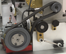
Multi-Belt Drive, Straight Tooth Gearbox, and Adjustable Particle Magnetic Brake System (M-BDGB) |
- Learn sheave misalignment and belt tension effects on vibration, and belt fault frequencies.
- Learn the effects of load, backlash, and tooth faults on the amplitudes and distribution of the gearmesh and sideband frequencies.
- Develop advanced signal processing techniques such as time synchronous averaging, wavelet analysis, short time Fourier transform for gearbox fault diagnosis.
- Develop expertise to diagnose a gearbox problem under a variable loading (or speed) conditions.
- Learn the effects of the frequency and amplitude modulation on vibration spectra.
- Remove the pinion assembly for backlash adjustment, and fault introduction.
- The kit consists of two V-belts, two double groove sheaves and one rolling tensioner; one three-way oil-lubricated gearbox with straight cut bevel gears, cup and cone roller bearings; and one manually adjustable magnetic brake.
|  |
Defective Straight Tooth Gearbox Pinions (Requires M-BDGB) (M-DGPA) |
- Study the effect of damaged tooth in gearboxes.
- Investigate backlash between mating gears.
- The kit consists of one missing tooth pinion and one chipped tooth pinion.
- Requires M-BDGB
- Learn the effects of the frequency and amplitude modulation on vibration spectra.
- Remove the pinion assembly for backlash adjustment, and fault introduction.
- The kit consists of two V-belts, two double groove sheaves and one rolling tensioner; one three-way oil-lubricated gearbox with straight cut bevel gears, cup and cone roller bearings; and one manually adjustable magnetic brake.
|  |
Worn Straight Tooth Gearbox (Requires M-BDGB) (M-WGB) |
- Develop practical techniques to diagnose gearbox faults, such as backlash, bearing looseness, and tooth surface polishing and imprint.
- Compare vibration spectral floor between new and worn gearboxes.
- The kit consists of one worn gearbox.
- Requires M-BDGB
- Learn the effects of the frequency and amplitude modulation on vibration spectra.
- Remove the pinion assembly for backlash adjustment, and fault introduction.
- The kit consists of two V-belts, two double groove sheaves and one rolling tensioner; one three-way oil-lubricated gearbox with straight cut bevel gears, cup and cone roller bearings; and one manually adjustable magnetic brake.
| |
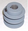
Eccentric Sheave (Requires M-BDGB) (M-ES-3/4) |
- Study the effects of eccentric sheaves.
- Distinguish between eccentricity, unbalance, belt resonance.
- The kit consists of one eccentric sheave
- Requires M-BDGB
- Learn the effects of the frequency and amplitude modulation on vibration spectra.
- Remove the pinion assembly for backlash adjustment, and fault introduction.
- The kit consists of two V-belts, two double groove sheaves and one rolling tensioner; one three-way oil-lubricated gearbox with straight cut bevel gears, cup and cone roller bearings; and one manually adjustable magnetic brake.
|  |
Belt-Drive Mounting Block (Requires M-BDGB) (M-BDB) |
- Learn sheave misalignment and belt tension effects on vibration, and belt fault frequencies without the gearbox imprint.
- Study belt response to variable magnetic brake loading.
- The kit consists of one belt-drive block.
- Requires M-BDGB
- Learn the effects of the frequency and amplitude modulation on vibration spectra.
- Remove the pinion assembly for backlash adjustment, and fault introduction.
- The kit consists of two V-belts, two double groove sheaves and one rolling tensioner; one three-way oil-lubricated gearbox with straight cut bevel gears, cup and cone roller bearings; and one manually adjustable magnetic brake.
| |
Direct Driven Gearbox Mounting Kit (Requires M-BDGB) (M-DGBB) |
- Study gearbox vibration signatures without belt, shaft or bearing imprint.
- The kit consists of all hardware needed to mount the gearbox directly the AC motor
- Requires M-BDGB
- Requires M-BDGB
- Learn the effects of the frequency and amplitude modulation on vibration spectra.
- Remove the pinion assembly for backlash adjustment, and fault introduction.
- The kit consists of two V-belts, two double groove sheaves and one rolling tensioner; one three-way oil-lubricated gearbox with straight cut bevel gears, cup and cone roller bearings; and one manually adjustable magnetic brake.
|  |
Reciprocating Mechanism (Requires M-BDGB) (M-RMS) |
- Monitor and diagnose reciprocation and load varying machinery.
- Study torsional vibration measurement techniques.
- Demonstrate the effectiveness of commercial analyzers at tracking speed variation and displaying the results.
- The kit consists of a reciprocating mechanism with two springs, adjustable spring engagement timing, and two stroke settings.
- Requires M-BDGB
- Remove the pinion assembly for backlash adjustment, and fault introduction.
- The kit consists of two V-belts, two double groove sheaves and one rolling tensioner; one three-way oil-lubricated gearbox with straight cut bevel gears, cup and cone roller bearings; and one manually adjustable magnetic brake.
|  |
Direct Driven Reciprocating Mechanism Mounting Kit (Requires M-RMS and M-BDGB) (M-DRMB) |
- Study reciprocating mechanism vibration signatures without gearbox, belt, shaft or bearing imprint.
- The kit consists of all hardware needed to mount the reciprocating mechanism directly the AC motor.
- Requires M-BDGB and M-RMS
- The kit consists of a reciprocating mechanism with two springs, adjustable spring engagement timing, and two stroke settings.
- Requires M-BDGB
- Remove the pinion assembly for backlash adjustment, and fault introduction.
- The kit consists of two V-belts, two double groove sheaves and one rolling tensioner; one three-way oil-lubricated gearbox with straight cut bevel gears, cup and cone roller bearings; and one manually adjustable magnetic brake.
|  |
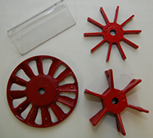
Fan Vibration Kit (M-FVK-3/4) |
- Learn the sound and vibration signatures of fans.
- Study the effects of volumetric flow rate on pressure rise and fan vibration.
- Develop the noise and vibration control methods on fans.
- The kit consists of one six-blade paddle fan, one ten-blade paddle fan, one 12-blade axial fan, and one axial fan obstruction
- Requires M-BDGB
- Remove the pinion assembly for backlash adjustment, and fault introduction.
- The kit consists of two V-belts, two double groove sheaves and one rolling tensioner; one three-way oil-lubricated gearbox with straight cut bevel gears, cup and cone roller bearings; and one manually adjustable magnetic brake.
|  |
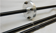
Crack Shaft Study Kit (M-CSRK-3/4) |
- Study the effects of crack on the natural frequencies and vibration behavior.
- Develop diagnostic technique to detect crack at early stage.
- Study crack propagation and breathing.
- Apply advanced signal processing techniques, such as wavelet, joint time-frequency analysis, time series analysis, to study the vibration caused by crack.
- The kit consists of one shaft with a 4 1/2″ 4-bolt flange connection to simulate crack, one shaft with slit crack and filler, and one shaft with a deep V-notch crack.
- Remove the pinion assembly for backlash adjustment, and fault introduction.
- The kit consists of two V-belts, two double groove sheaves and one rolling tensioner; one three-way oil-lubricated gearbox with straight cut bevel gears, cup and cone roller bearings; and one manually adjustable magnetic brake.
|  |
Mechanical Rub Kit (M-MRK) |
- Evaluate typical rub phenomena associated with a variety of materials under different angle, loading, and lubricant conditions.
- Experiment rubs on shaft or rotor.
- The kit consists of an adjustable spring-loader rub material holder and four different rub materials
- Apply advanced signal processing techniques, such as wavelet, joint time-frequency analysis, time series analysis, to study the vibration caused by crack.
- The kit consists of one shaft with a 4 1/2″ 4-bolt flange connection to simulate crack, one shaft with slit crack and filler, and one shaft with a deep V-notch crack.
- Remove the pinion assembly for backlash adjustment, and fault introduction.
- The kit consists of two V-belts, two double groove sheaves and one rolling tensioner; one three-way oil-lubricated gearbox with straight cut bevel gears, cup and cone roller bearings; and one manually adjustable magnetic brake.
|  |
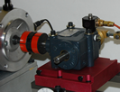
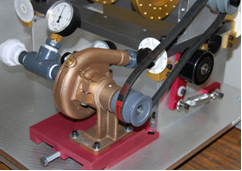
Centrifugal Pump with Clear Cover to Visualize Cavitation (Requires M-BDGB) (M-CFPK) |
- Study vibration spectra due to cavitation.
- Determine the damaging effect of the cavitation.
- Visualize cavitation using the clear pump cover.
- Study the effect of turbulence on vibration signature.
- Study the effect on pump loading on motor and other components.
- Study the effect of different head and valve restriction on suction and/or discharge sides on flow dynamics of the pump.
- Investigate the effect of speed and load variation on pump vibration spectra.
- Study the effect of clearance between the impeller and the suction portion of the pump.
- Conduct similar studies using other non-hazardous liquids of different viscosity and specific gravity.
- The kit consists of one single stage centrifugal pump, one LEXAN cover for visualizing cavitation, two pressure gauges, one flow meter, one water tank, all connecting valves and hoses, one sheave, and mounting hardware
- Requires M-BDGB
|  |
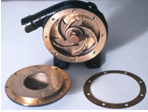
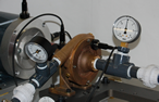
Centrifugal Pump With Worn Impeller (Requires M-BDGB and M-CFPK) (M-CFPFI) |
- Recognize vibration and hydraulic issues associated with a worn pump.
- The kit consists of one worn centrifugal pump with simulated cavitation damage to the head and impeller.
- Requires M-BDGB and M-CFPK
- Study the effect of turbulence on vibration signature.
- Study the effect on pump loading on motor and other components.
- Study the effect of different head and valve restriction on suction and/or discharge sides on flow dynamics of the pump.
- Investigate the effect of speed and load variation on pump vibration spectra.
- Study the effect of clearance between the impeller and the suction portion of the pump.
- Conduct similar studies using other non-hazardous liquids of different viscosity and specific gravity.
- The kit consists of one single stage centrifugal pump, one LEXAN cover for visualizing cavitation, two pressure gauges, one flow meter, one water tank, all connecting valves and hoses, one sheave, and mounting hardware
- Requires M-BDGB
|  |
Direct Driven Centrifugal Pump Mounting Kit (M-CFPK) (M-DCPK) |
- Study centrifugal pump vibration signatures without belt, shaft or bearing imprint.
- The kit consists of all hardware needed to mount the centrifugal pump directly the AC motor
- Requires M-CFPK
- Study the effect of turbulence on vibration signature.
- Study the effect on pump loading on motor and other components.
- Study the effect of different head and valve restriction on suction and/or discharge sides on flow dynamics of the pump.
- Investigate the effect of speed and load variation on pump vibration spectra.
- Study the effect of clearance between the impeller and the suction portion of the pump.
- Conduct similar studies using other non-hazardous liquids of different viscosity and specific gravity.
- The kit consists of one single stage centrifugal pump, one LEXAN cover for visualizing cavitation, two pressure gauges, one flow meter, one water tank, all connecting valves and hoses, one sheave, and mounting hardware
- Requires M-BDGB
|  |
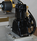
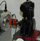
Reciprocating Compressor Kit (Requires M-BDGB) (M-RCK) |
- Learn the sound and vibration signatures of compressor housing, valves, and other structural components.
- Develop diagnosis techniques for reciprocating compressors.
- Learn the reciprocating compressor performance.
- Study the pressure pulsation and the effects of discharge pressure on the behavior of the compressor.
- The kit consists of one 1/2 HP compressor, one 5-gallon air tank with flow controls, all needed piping and mounting hardware.
- Requires M-BDGB
- Investigate the effect of speed and load variation on pump vibration spectra.
- Study the effect of clearance between the impeller and the suction portion of the pump.
- Conduct similar studies using other non-hazardous liquids of different viscosity and specific gravity.
- The kit consists of one single stage centrifugal pump, one LEXAN cover for visualizing cavitation, two pressure gauges, one flow meter, one water tank, all connecting valves and hoses, one sheave, and mounting hardware
- Requires M-BDGB
|  |
Reciprocating Compressor Fault Kit (Requires M-BDGB and M-RCK) (M-RCFK) |
- Learn the sound and vibration signatures of compressor with faulty valves
- The kit consists of one ½ HP compressor with leaking valve, blocked suction filter, limited opening discharge valve, and oversized connecting rod.
- Requires M-BDGB and M-RCK
- Study the pressure pulsation and the effects of discharge pressure on the behavior of the compressor.
- The kit consists of one 1/2 HP compressor, one 5-gallon air tank with flow controls, all needed piping and mounting hardware.
- Requires M-BDGB
- Investigate the effect of speed and load variation on pump vibration spectra.
- Study the effect of clearance between the impeller and the suction portion of the pump.
- Conduct similar studies using other non-hazardous liquids of different viscosity and specific gravity.
- The kit consists of one single stage centrifugal pump, one LEXAN cover for visualizing cavitation, two pressure gauges, one flow meter, one water tank, all connecting valves and hoses, one sheave, and mounting hardware
- Requires M-BDGB
| |
Direct Driven Reciprocating Compressor Mounting Kit (M-RCK) (M-DRCK) |
- Study reciprocating compressor vibration signatures without belt, shaft or bearing imprint.
- The kit consists of all hardware needed to mount the reciprocating compressor directly the AC motor
- Requires M-RCK
- Study the pressure pulsation and the effects of discharge pressure on the behavior of the compressor.
- The kit consists of one 1/2 HP compressor, one 5-gallon air tank with flow controls, all needed piping and mounting hardware.
- Requires M-BDGB
- Investigate the effect of speed and load variation on pump vibration spectra.
- Study the effect of clearance between the impeller and the suction portion of the pump.
- Conduct similar studies using other non-hazardous liquids of different viscosity and specific gravity.
- The kit consists of one single stage centrifugal pump, one LEXAN cover for visualizing cavitation, two pressure gauges, one flow meter, one water tank, all connecting valves and hoses, one sheave, and mounting hardware
- Requires M-BDGB
|  |
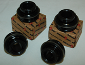
Damped Bearing Housing Kit (Requires MR-SCK -3/4) (M-DBHK-1/2) |
- Study bearing housing with a higher damping factor than the standard housing. Typical rolling element bearing systems are an all-metal structure with virtually no damping.
- Add damping to a standard rolling element bearing housing.
- Demonstrate the reduction in rotor resonance amplitude due to the installation of damping.
- The kit consists of two bearing housings and two 1/2″ bearings fitted with isolators.
- Requires M-RSK-1/2
- Requires M-BDGB
- Investigate the effect of speed and load variation on pump vibration spectra.
- Study the effect of clearance between the impeller and the suction portion of the pump.
- Conduct similar studies using other non-hazardous liquids of different viscosity and specific gravity.
- The kit consists of one single stage centrifugal pump, one LEXAN cover for visualizing cavitation, two pressure gauges, one flow meter, one water tank, all connecting valves and hoses, one sheave, and mounting hardware
- Requires M-BDGB
|  |
AC Motor With Built-In Rotor Unbalance (M-UBM) |
- Study the effects of unbalanced rotor on vibration and/or current signature.
- Study the effect of unbalance rotor on power quality and consumption.
- Study the effect of temperature rise on non-linear characteristics of induction motors.
- The kit consists of one unbalanced 1/2 HP AC motor
- Requires M-RSK-1/2
- Requires M-BDGB
- Investigate the effect of speed and load variation on pump vibration spectra.
- Study the effect of clearance between the impeller and the suction portion of the pump.
- Conduct similar studies using other non-hazardous liquids of different viscosity and specific gravity.
- The kit consists of one single stage centrifugal pump, one LEXAN cover for visualizing cavitation, two pressure gauges, one flow meter, one water tank, all connecting valves and hoses, one sheave, and mounting hardware
- Requires M-BDGB
| |
AC Motor With Built-In Rotor Misalignment System (M-MAM) |
- Study the effect of variable air gap on vibration and/or current signature.
- Study the effect of amount/type of misalignment and rotor speed on vibration/current spectra.
- Determine the effect of misalignment on power quality and consumption.
- Study the effect of temperature rise on non-linear characteristics of induction motors.
- The kit consists of one 1/2 HP AC motor with custom machined end bells, which allows for easy introduction of known misalignment at either end of the motor.
- Requires M-BDGB
- Investigate the effect of speed and load variation on pump vibration spectra.
- Study the effect of clearance between the impeller and the suction portion of the pump.
- Conduct similar studies using other non-hazardous liquids of different viscosity and specific gravity.
- The kit consists of one single stage centrifugal pump, one LEXAN cover for visualizing cavitation, two pressure gauges, one flow meter, one water tank, all connecting valves and hoses, one sheave, and mounting hardware
- Requires M-BDGB
| |
AC Motor With Built-In Bowed Rotor (M-BRM) |
- Study the effects of rotor bow on vibration and/or current signature.
- Study the effect of bowed rotor on power quality and consumption.
- The kit consists of one 1/2 HP AC motor with centrally bent rotor
- Study the effect of temperature rise on non-linear characteristics of induction motors.
- The kit consists of one 1/2 HP AC motor with custom machined end bells, which allows for easy introduction of known misalignment at either end of the motor.
- Requires M-BDGB
- Investigate the effect of speed and load variation on pump vibration spectra.
- Study the effect of clearance between the impeller and the suction portion of the pump.
- Conduct similar studies using other non-hazardous liquids of different viscosity and specific gravity.
- The kit consists of one single stage centrifugal pump, one LEXAN cover for visualizing cavitation, two pressure gauges, one flow meter, one water tank, all connecting valves and hoses, one sheave, and mounting hardware
- Requires M-BDGB
| |
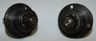
AC Motor With Built-In Faulted Bearings (M-FBM) |
- Study the effects of bearing faults on vibration and/or current signature.
- Study the effect of bearing faults on power quality and consumption.
- The kit consists of one 1/2 HP AC motor fitted with one inner race faulted bearing and one with outer race faulted bearing. User can specify the types of bearing faults.
- Study the effect of temperature rise on non-linear characteristics of induction motors.
- The kit consists of one 1/2 HP AC motor with custom machined end bells, which allows for easy introduction of known misalignment at either end of the motor.
- Requires M-BDGB
- Investigate the effect of speed and load variation on pump vibration spectra.
- Study the effect of clearance between the impeller and the suction portion of the pump.
- Conduct similar studies using other non-hazardous liquids of different viscosity and specific gravity.
- The kit consists of one single stage centrifugal pump, one LEXAN cover for visualizing cavitation, two pressure gauges, one flow meter, one water tank, all connecting valves and hoses, one sheave, and mounting hardware
- Requires M-BDGB
| |
AC Motor With Built-In Broken Rotor Bars (M-BRBM) |
- Study the effect of broken rotor bars on motor vibration and/or current signature as a function of speed and load.
- Study the effect of broken rotor bars on power quality and consumption.
- Study the effect of temperature rise on non-linear characteristics of induction motors.
- The kit consists of one 1/2 HP AC motor with broken rotor bars
- The kit consists of one 1/2 HP AC motor with custom machined end bells, which allows for easy introduction of known misalignment at either end of the motor.
- Requires M-BDGB
- Investigate the effect of speed and load variation on pump vibration spectra.
- Study the effect of clearance between the impeller and the suction portion of the pump.
- Conduct similar studies using other non-hazardous liquids of different viscosity and specific gravity.
- The kit consists of one single stage centrifugal pump, one LEXAN cover for visualizing cavitation, two pressure gauges, one flow meter, one water tank, all connecting valves and hoses, one sheave, and mounting hardware
- Requires M-BDGB
| |
AC Motor With Stator Winding Faults (M-SSTM) |
- Study the effects of turn-to-turn short in stator windings on vibration and/or current signature.
- Study the effect of turn-to-turn short in stator windings on power quality and consumption.
- Study the effect of temperature rise on non-linear characteristics of induction motors.
- The kit consists of one 1/2 HP AC motor with shorted stator winding turns, and one control box to vary short conditions.
- The kit consists of one 1/2 HP AC motor with custom machined end bells, which allows for easy introduction of known misalignment at either end of the motor.
- Requires M-BDGB
- Investigate the effect of speed and load variation on pump vibration spectra.
- Study the effect of clearance between the impeller and the suction portion of the pump.
- Conduct similar studies using other non-hazardous liquids of different viscosity and specific gravity.
- The kit consists of one single stage centrifugal pump, one LEXAN cover for visualizing cavitation, two pressure gauges, one flow meter, one water tank, all connecting valves and hoses, one sheave, and mounting hardware
- Requires M-BDGB
| |
AC Motor With Voltage Unbalance & Single Phasing (M-VUSM) |
- Study the effects of voltage unbalance and one phase loss on motor current/vibration signatures.
- Study the effect of voltage unbalance and one phase loss on power quality and consumption.
- Study the effect of temperature rise on non-linear characteristics of induction motors
- The kit consists of one 1/2 HP AC motor and one control box to vary voltage balance and to disconnect one phase.
- The kit consists of one 1/2 HP AC motor with custom machined end bells, which allows for easy introduction of known misalignment at either end of the motor.
- Requires M-BDGB
- Investigate the effect of speed and load variation on pump vibration spectra.
- Study the effect of clearance between the impeller and the suction portion of the pump.
- Conduct similar studies using other non-hazardous liquids of different viscosity and specific gravity.
- The kit consists of one single stage centrifugal pump, one LEXAN cover for visualizing cavitation, two pressure gauges, one flow meter, one water tank, all connecting valves and hoses, one sheave, and mounting hardware
- Requires M-BDGB
| |
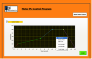
PC Motor Control Kit (M-PCK) |
- Operate MFS from remote location.
- Pre-program speed acceleration, deceleration, and length of run to meet exact requirements.
- The kit consists of PC software, one interface module to motor drive and cables.
- The kit consists of one 1/2 HP AC motor and one control box to vary voltage balance and to disconnect one phase.
- The kit consists of one 1/2 HP AC motor with custom machined end bells, which allows for easy introduction of known misalignment at either end of the motor.
- Requires M-BDGB
- Investigate the effect of speed and load variation on pump vibration spectra.
- Study the effect of clearance between the impeller and the suction portion of the pump.
- Conduct similar studies using other non-hazardous liquids of different viscosity and specific gravity.
- The kit consists of one single stage centrifugal pump, one LEXAN cover for visualizing cavitation, two pressure gauges, one flow meter, one water tank, all connecting valves and hoses, one sheave, and mounting hardware
- Requires M-BDGB
|  |
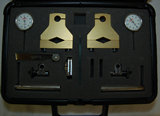
Shaft Alignment Kit (M-ATK) |
- Align shafts precisely with convenient and simple Windows alignment software.
- Accommodates 1/2″ to 1 1/4″ diameter shafts.
- The kit consists of two precision dial indicators, two mounting brackets/bars, one mirror, one set of feeler gauges, and instructions packaged in a rugged plastic case.
- The kit consists of one 1/2 HP AC motor and one control box to vary voltage balance and to disconnect one phase.
- The kit consists of one 1/2 HP AC motor with custom machined end bells, which allows for easy introduction of known misalignment at either end of the motor.
- Requires M-BDGB
- Investigate the effect of speed and load variation on pump vibration spectra.
- Study the effect of clearance between the impeller and the suction portion of the pump.
- Conduct similar studies using other non-hazardous liquids of different viscosity and specific gravity.
- The kit consists of one single stage centrifugal pump, one LEXAN cover for visualizing cavitation, two pressure gauges, one flow meter, one water tank, all connecting valves and hoses, one sheave, and mounting hardware
- Requires M-BDGB
|  |
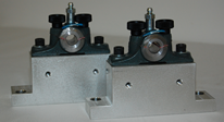
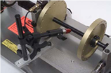
Mechanically Operated Bearing Loader (M-MBL-3/4) |
- Investigate bearing radial loading effects.
- Understand bearing failure signature as a function of load and rotational speed.
- Compare vibration signature between loaded and unloaded bearings.
- Study outer race bearing fault signature as a function of load location.
- The kit consists of one bearing housing allowing for radial loading via threaded bolt.
- Requires M-BDGB
- Investigate the effect of speed and load variation on pump vibration spectra.
- Study the effect of clearance between the impeller and the suction portion of the pump.
- Conduct similar studies using other non-hazardous liquids of different viscosity and specific gravity.
- The kit consists of one single stage centrifugal pump, one LEXAN cover for visualizing cavitation, two pressure gauges, one flow meter, one water tank, all connecting valves and hoses, one sheave, and mounting hardware
- Requires M-BDGB
| |
Bearing Loader Force Transducer (Requires M-MBL-3/4) (M-BLFT) |
- Measure the radial load applied by the mechanically operated bearing loader.
- The kit consists of one transducer measuring radial force and one matching signal conditioner.
- Requires M-MBL-3/4
- Study outer race bearing fault signature as a function of load location.
- The kit consists of one bearing housing allowing for radial loading via threaded bolt.
- Requires M-BDGB
- Investigate the effect of speed and load variation on pump vibration spectra.
- Study the effect of clearance between the impeller and the suction portion of the pump.
- Conduct similar studies using other non-hazardous liquids of different viscosity and specific gravity.
- The kit consists of one single stage centrifugal pump, one LEXAN cover for visualizing cavitation, two pressure gauges, one flow meter, one water tank, all connecting valves and hoses, one sheave, and mounting hardware
- Requires M-BDGB
| |
Vertical and Horizontal Bearing Force Transducer for 1/2″ to 1″ Shafts (M-FTVH) |
- Measure forces exerted on bearings due to coupling misalignment, rotor unbalance, belt misalignment, and belt tension.
- Establish quantitative tensions for drive belt studies.
- Learn to relate the vibration signature to forces associated with common malfunctions such as resonance and bearing faults. Learn phase relationship between force and vibration spectrum.
- Learn nature of rotor dynamic forces due to common defects.
- Witness 180 degree phase shift between heavy and high spots when rotor goes through a critical speed. Demonstrate how mass unbalance force quadruples when the speed is doubled, but vibration amplitude does not follow the same trend.
- Verify and refine your rotor dynamic models and enhance modeling skills.
- The kit consists of one transducer simultaneously measuring vertical and horizontal force and one matching signal conditioner.
- Study the effect of clearance between the impeller and the suction portion of the pump.
- Conduct similar studies using other non-hazardous liquids of different viscosity and specific gravity.
- The kit consists of one single stage centrifugal pump, one LEXAN cover for visualizing cavitation, two pressure gauges, one flow meter, one water tank, all connecting valves and hoses, one sheave, and mounting hardware
- Requires M-BDGB
|  |
Axial Bearing Force Transducer for 1/2″ to 1″ shafts (M-FTA) |
- Measure the axial load on the main shaft under dynamic excitation.
- Investigate the effect of misaligned shaft and belts on the shaft axial load.
- Study the effects of cocked rotors and eccentric sheaves on the shaft axial load.
- The kit consists of one transducer measuring axial force on main shaft and one matching signal conditioner.
- Witness 180 degree phase shift between heavy and high spots when rotor goes through a critical speed. Demonstrate how mass unbalance force quadruples when the speed is doubled, but vibration amplitude does not follow the same trend.
- Verify and refine your rotor dynamic models and enhance modeling skills.
- The kit consists of one transducer simultaneously measuring vertical and horizontal force and one matching signal conditioner.
- Study the effect of clearance between the impeller and the suction portion of the pump.
- Conduct similar studies using other non-hazardous liquids of different viscosity and specific gravity.
- The kit consists of one single stage centrifugal pump, one LEXAN cover for visualizing cavitation, two pressure gauges, one flow meter, one water tank, all connecting valves and hoses, one sheave, and mounting hardware
- Requires M-BDGB
| |