


Critical Speeds in Rotating Machinery
Mohsen Nakhaeinejad & Suri GaneriwalaSpectraQuest Inc., 8227 Hermitage Road, Richmond, VA 23228
Published: October, 01 2008
Abstract
Critical speeds of rotating machinery in presence of different couplings and bearing faults are studied. A rotating machine including motor, coupling, rolling element bearings, shaft and disks was modeled in XLRotor, a powerful software for rotordynamics analysis. Effects of rotor/disks configurations and coupling stiffness on critical speeds were studied. The SpectraQuest Machinery Fault Simulator (MFS) Magnum was used to conduct series of experiments with four types of coupling: beam, lovejoy, gear and rigid couplings with different shaft/disk configurations. Also, bearing faults were introduced to the machine and the change of critical speeds was observed. Observations validate the XLRotor model and show the critical speed behavior of the MFS machine.
Introduction
All objects exhibit at least one natural frequency. This is the frequency at which the object will vibrate if struck once. The classic example is a bell or tuning fork. Resonance occurs when the object is repeatedly excited at the natural frequency. Physically, energy is confined within the boundaries of the structure and cannot escape or dissipate quickly, creating standing wave deformations at the natural frequencies. The standing waves displaying the actual motion at a natural frequency are known as mode shapes. Since resonance results in large amplitudes that can be both noisy and destructive, good machine design calls for avoiding such conditions. As a result, in designing a machine, modeling and calculations are performed to estimate the natural frequencies of the various parts and the entire structure. With this knowledge, the machine design can be altered during the design stages to avoid resonant conditions.
The expression critical speed or simply critical applies to a rotating system, particularly shaft and rotors, as opposed to stationary structures. The critical speed of a rotating system occurs when the rotational speed matches a natural frequency. Resonance occurs as the rotating speed passes through each natural frequency. Minimizing rotational unbalance and unnecessary external forces are very important to reducing the overall forces, which initiate resonance. The lowest speed at which a natural frequency is encountered is called the first critical. As the speed increases, additional critical speeds may be observed. For example, there might be second and third criticals. Critical speeds significantly greater than the maximum operating speed of the machine are of less interest and importance.
Since the real dynamics of machines in operation is difficult to model theoretically, calculations are based on the simplified model which resembles the various structural components. Obtained equations from models can be solved either analytically or numerically. Also, Finite Element Methods (FEM) is another approach for modeling and analysis of the machine for natural frequencies. Resonance tests to confirm the precise frequencies are often performed on the prototype machine and then the design revised as necessary to assure that resonance does not become an issue. In addition, resonance testing may be required when troubleshooting the machine or components that experience unexpected failures or short lives. Transient or startup/coastdown test which is used in this study is an excellent way to quickly scan the whole machine for natural. The machine starts up and accelerates to a maximum speed and coast down to the rest with constant acceleration and deceleration rates. The machine is excited by itself as the dynamic forces come into play. Vibration signals are collected and the high spectral peaks represent the natural frequencies.
The objective of this technical note is to study the critical speeds in rotating machinery. To achieve this goal, a rotating system including motor, shaft, disks, coupling and rolling element bearings is considered and the XLRotor is used for modeling and analysis. The stiffness and damping associated with the rolling element bearings are calculated in software and the whole rotating system is solved for damped critical speeds. Experiments were conducted on a SpectraQuest’s Machinery Fault Simulator (MFS) Magnum to validate the XLRotor data. Also, changes of critical speeds due to locations of disks on the shaft, type of coupling and faulted bearings were studied by experiments.
![]()
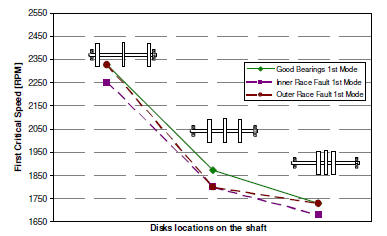
Fig 1: Effect of bearing faults on the 1st (left) critical speed. Inner race and outer race faults are introduced on the left bearing.
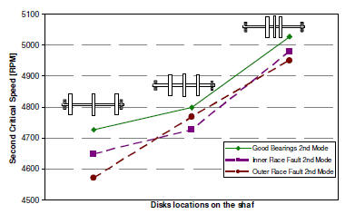
Fig 2: Effect of bearing faults on the 2nd (right) critical speed. Inner race and outer race faults are introduced on the left bearing.