


Vibration Signature of Defected Gear Tooth Using Spectral Analysis
Zhuang Li & Suri GaneriwalaSpectraQuest Inc., 8227 Hermitage Road, Richmond, VA 23228
Published: August, 01 2007
Abstract
The vibration signature of gear tooth seeded fault has been studied in this tech note. Experiments were carried out on Spectra Quest’s Gear box Dynamics Simulator (GDS). The test rig simulates a two-stage parallel gear transmission. The input gear in the gearbox was intentionally faulted with increasing severity level. For each gear configuration, tests were conducted with and without loading applied by a magnetic brake. The experimental results show that due to the impact caused by the faulted tooth, strong sidebands arise around the meshing frequency in the spectra. At high severity level, the amplitudes of the sidebands may be even higher than that of the meshing frequency components
Introduction
Gearboxes are very commonly used in industry as well as in vehicles. During their extended service lifetimes, gear teeth will inevitably be worn, chipped, or even missing under high load. Therefore effective diagnostic methods are required in order to enhance the reliability of the entire machine before any unexpected catastrophic consequences occur. The vibration-based techniques are the most widely used since it is easy to obtain the acceleration signals using accelerometers. The gear diagnostic parameters include RMS value, crest factor, kurtosis, energy ratio, and other metrics. They are all statistical methods. Advanced techniques, such as joint time-frequency analysis, wavelet, and neural networks, have been successfully applied to the gear fault diagnostics.
Experiments in this article were conducted on Spectra Quest’s Gearbox Dynamics Simulator (GDS). Instead of a one-stage transmission, a two-stage transmission with spur gears was investigated. The objective of these experiments is to relate the development of the frequency component changes to the severity level.
The GDS is a specially designed platform for studying signatures of common gearing faults. Spur or helical gears can be fitted into a two-stage parallel shaft design. The gearbox is driven by a 3 HP motor with a speed range of 0~3600 rpm. The inverter can be programmed for higher speeds, but care must be exercised to assure proper lubrication and temperature control. Load can be applied using the magnetic brake. The loading force is controlled by a current source. The modular design of the gearbox allows one to introduce various faults, such as chipped, broken and cracked teeth, gear eccentricity, and worn gear, either individually or jointly in a totally controlled environment. The gears can be set up at different locations along the shaft in order to alter system stiffness and make room for additional devices. The GDS is also a test bed for analyses in gear noise, loading effect and fault diagnosis techniques
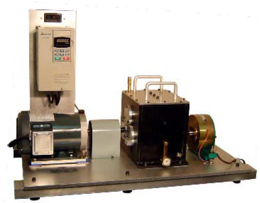
Fig 1: Gearbox Dynamics Simulator
Fig 2: Gearbox acceleration spectra without load-24-tooth gear with a large chip
Fig 3: Gearbox acceleration spectra with load-24-tooth gear with a large chip