


Torsional Vibration Simulation Using a Universal Joint
Zhuang Li, Mohsen Nakhaeinejad & Suri GaneriwalaSpectraQuest Inc., 8227 Hermitage Road, Richmond, VA 23228
Published: January, 01 2009
Abstract
A universal joint is a mechanical device which can transmit torque and rotational motion of two intersecting shafts. The joint consists of a pair of yokes oriented at 90o relative to each other. The two yokes are called the driving and driven yokes. This document introduces the basic theory of the speed variation caused by a universal joint. Measurements were conducted using SpectraQuest Torsional Vibration Calibrator. Conclusions can be drawn from both the theoretical and experimental analyses. A non-zero joint angle of a universal joint causes the output shaft speed varies with an averaged speed the same as the input speed. It is used to simulate the torsional vibration of the output shaft. The amplitude of the speed variation increases with the joint angle, and is linearly proportional to the averaged speed. The angular variation, however, only depends on the joint angle, but is not a function of the angular speed.
Introduction
A universal joint is a mechanical device which can transmit torque and rotational motion of two intersecting shafts. The joint consists of a pair of yokes oriented at 90o relative to each other. The two yokes are called the driving and driven yokes.
Experiments were carried out on the SpectraQuest Torsional Vibration Calibrator (TVC), shown in Fig. 2. The TVC is driven by a 3-HP motor whose speed is controlled by a VFD. A flywheel is used to stabilize the input shaft speed. The input and output shafts are connected using a Cardan universal joint, where the joint angle can be adjusted. A series of holes on the base plate allow users to adjust the joint angle from -20o to +20o with an increment of 2.5o.
The angular speed of the output shaft was measured using a 1024-pulse encoder. The encoder output was connected to one of the counter/timer channels on the National Instrument PCI 6221 data acquisition board. The time base and size of the counter/timer are 80 MHz and 32-bit, respectively. The counter/timer recorded the time of occurrence each pulse. Calculating the time variance of the time intervals between pulses gives the angular speed variation of the output shaft.
Three joint angles were tests: 5o, 10o, and 15o. At each joint angle, the encoder data were collected at different running speeds.
![]()
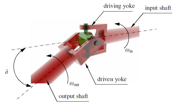
Fig 1: Cardan universal joint
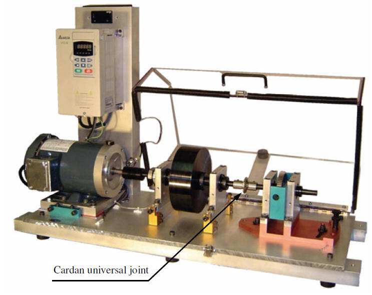
Fig 2: Torsional Vibration Calibrator