


Vibration and Force Signatures of Overhung Rotor Rotating Machine with Unknown Initial Conditions
Eric Li, Zhuang Li & Suri GaneriwalaSpectraQuest Inc., 8227 Hermitage Road, Richmond, VA 23228
Published: July, 01 2008
Abstract
Rotating machinery with overhung rotors is very common in industry. Unbalanced rotor and misaligned shafts usually causes excessive machine vibration, generates large forces on bearings and thus reduces the machine life span and may lead to property loss and even human life loss. Two-plane balancing of overhung rotors is one of the most challenge problems maintenance engineers may encounter. As a prerequisite, Successful diagnosis of unbalanced overhung rotor system must be performed. The vibration and force signatures of unbalanced overhung rotors with unknown initial conditions are different from those of the systems with center hung rotors and have been studied in this tech note. Experiments were carried out on a Machinery Fault Simulator(MFS) for both balanced and unbalanced rotor systems. The data were analyzed using the VibraQuestTM software and efforts were focused on identifying the system characteristic signatures.
Introduction
Unbalance is one of the most common reasons of excessive machine vibration. It has been said that 80% of the vibration problems of the rotating machinery can be solved by balancing and alignments. A small amount of unbalance weight in rotating system may have devastating effects as the system is operating with high speed or running near the critical speed. Therefore, extreme care must be taken in balancing high speed rotating system to avoid any potential damages. Overhung rotors are commonly used in fluid turbo-machinery, such as pumps, propellers and fans. The vibration and force signatures of the overhung rotors are different from that of the center hung rotors, which have been well studied.
The vibration and force signatures of unbalanced overhung rotor can be simply explained as below: the unbalance forces will cause the bearing to move in a circle in its own plane. when the force is upward on the outboard bearing, the tilting of the bearing will be away from the rotor, so the axial phase at the top of the bearing will be out of phase with the vertical. At the inboard bearing (the one away from the overhung rotor), the situation is reversed relative to the outboard bearing at any given time. When the rotor is forcing the inboard bearing upward, it will force the outboard bearing downward, so the vertical phases will be 180 degrees apart between the two bearings. Also, the bending of the shaft between the bearings will causes the inboard bearing to tilt toward the rotor, opposite to the tilt of the outboard bearing. Therefore, the axial phase at the top of the inboard bearing will be out of phase with the vertical.
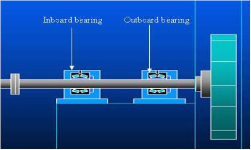
Fig 1: Configuration of Single Plane Overhung Rotor
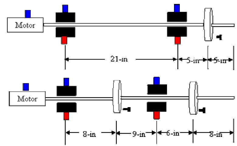
Fig 2: Dimensions of the Test Rig (a) one rotor overhung (b) one centered and one overhung (Blue: Triaxial accelerometer; Red: Force transducer)
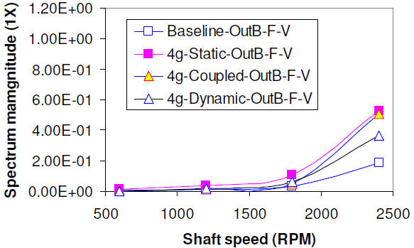
Fig 3: 1X spectrum magnitude of the bearing housing vertical force as function of shaft speed and unbalance weight: outboard