


State of the Art in Monitoring Rotating Machinery-Part 1
Robert B. RandallThe University of new South Wales, Sydney, Australia
Published:
Abstract
In the last thirty years there have been many developments in the use of vibration measurement and analysis for monitoring the condition of rotating machinery while in operation. These have been in all three areas of interest, namely fault detection, diagnosis and prognosis. Of these areas, diagnosis and prognosis still require an expert to determine what analyses to perform and to interpret the results. Currently much effort is being put into automating fault diagnosis and prognosis. Major economic benefits come from being able to predict with reasonable certainty how much longer a machine can safely operate (often a matter of several months from when incipient faults are first detected). This article discusses the different requirements for detecting and diagnosing faults, outlining a robust procedure for the former, and then goes on to discuss a large number of signal processing techniques that have been proposed for diagnosing both the type and severity of the faults once detected. Change in the severity can of course be used for prognostic purposes. Most procedures are illustrated using actual signals from case histories.
Introduction
The vibrations measured externally on operating machines contain much information about their condition, as machines in normal condition have a characteristic "vibration signature," while most faults change this signature in a well-defined way. Thus, vibration analysis is a w ay of getting information from the inside of operating machines without having to shut them down. Another way of getting information from operating machines is by analysis of the lubricant, and "oil analysis" is useful in machine condition monitoring. This article is concerned only with vibration analysis techniques.
Machine vibrations are measured in two fundamentally different ways – relative displacement of a shaft in its bearings using so-called "proximity probes," and absolute motion of the casing (usually at the bearings) using absolute motion transducers. Proximity probes must be designed into the machines and are typically used on high speed turbomachines with fluid film bearings. They are used for permanent monitoring of relatively simple parameters such as peak-to-peak relative displacement and shaft orbits (in the bearing) and are primarily used to protect valuable and critical machines by shutting them down in the event of excessive vibration. Only in a limited number of situations can long term predictions be made. This is because incipient faults often show up first at high frequencies, to which the relative displacement measurements are not sensitive. Proximity probes have a frequency range up to 10 kHz, but because of the natural reduction of displacement amplitudes with frequency and the dynamic range limitation of proximity probes to 30-40 dB, the limitation is really of harmonic order (to about 10-12 harmonics). The dynamic range limitation is determined mainly by electrical and mechanical runout, i.e. the signal measured in the absence of vibration. The higher dynamic range limit corresponds to the use of "runout subtraction," where the runout measured at low speed can be subtracted from other measurements at high speed. This technique is somewhat dubious over long periods of time where the originally measured runout may have changed.
Since all vibrations represent an alternation between potential energy (in the form of strain energy) and kinetic energy, vibration velocity is the parameter most closely related to stress, and is the parameter used to evaluate severity in most vibration criteria. For the same reason, a velocity spectrum is usually 'flattest' over a wide frequency range, requiring the minimum dynamic range to represent all important components. By comparison, vibration displacement tends to overemphasize low frequencies (as for relative displacement) while vibration acceleration tends to over-emphasize high frequencies. The latter can sometimes be useful for faults, such as in rolling element bearings, which show up first at high frequencies, but may disguise changes at low frequencies. However, the best and most common transducer for measuring absolute casing vibration is the piezoelectric accelerometer which produces a signal proportional to acceleration. Its dynamic range is so large (160 dB) that it can be combined with electronic integration to give a velocity signal with more than 60 dB dynamic range over three decades in frequency. This cannot be achieved by typical velocity transducers with an upper frequency limit of 1-2 kHz. For these reasons, the rest of this article mostly assumes measurements made with accelerometers, sometimes integrated to velocity. The meaning of "rotating machines" has been taken to include reciprocating machines such as diesel engines. Because of their importance and ubiquity, the measurement of torsional vibration of the crankshaft is included as a supplementary technique.
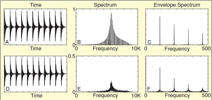
Fig 1: Bearing fault pulses with and without frequency fluctuation; (A, B, C) no frequency fluctuation; (D, E, F) 0.75% random frequency fluctuation.