| PERFORMANCE |
ENGLISH |
SI |
| Measurement Range |
0.0 to 2 in/sec pk |
|
| Output |
4-20 mA |
|
| Frequency Range(± 10 %)
|
180 to 60,000 cpm |
|
| Broadband Resolution |
0.01 in/sec pk |
|
| Non-Linearity |
± 1 % |
|
| ENVIRONMENTAL |
|
|
| Temperature Range |
-40 to 185 °F |
|
| ELECTRICAL |
|
|
| Excitation Voltage |
12 to 30 VDC |
|
| Settling Time(within 2% of
value) |
<15 sec |
|
| Electrical
Isolation(Case) |
>108 ohm
|
|
| PHYSICAL |
|
|
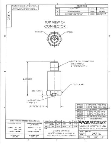
| Size (Hex x Height) |
1.0 in x 2.6 in |
|
| Weight |
4.7 oz |
|
| Mounting Thread |
1/4-28 UNF |
|
| Mounting Torque |
3 to 5 ft-lb |
|
| Sensing Element |
Ceramic |
|
| Sensing Geometry |
Shear |
|
| Housing Material |
Stainless Steel |
|
| Sealing |
Welded Hermetic |
|
| Electrical Connector |
2-Pin MIL-C-5015 |
|
| Electrical Connection
Position |
Top |
|
| Electrical Connections(Pin
A) |
4-20 mA Pos (+) |
|
| Electrical Connections(Pin
B) |
4-20 mA Neg (-) |
|
| SUPPLIED ACCESSORIES:
|
| Model 081A40 Mounting Stud
(1) |
| Model ICS-4 NIST-traceable
single-axis amplitude response calibration from 0 cpm (0 Hz)
to upper 10% frequency for 4 - 20 mA output vibration sensor
(1) |
| OPTIONAL
VERSIONS |
| EX- Hazardous
Area Approval- contact factory for specific
approvals |
| |
| Hazardous Area
Approval |
DIV II, CL I, GRPS
A-D, ExnL, AExnA, IIC T4 |
|
| Hazardous Area
Approval |
EEx ia IIC T4,
-40°C≤Ta≤80°C, II 1 G |
|
| Hazardous Area
Approval |
EEx nL IIC T4,
-40°C≤Ta≤80°C, II 3 G |
|
| Hazardous Area
Approval |
DIV I, CL I, II,
III, GRPS A-G, Exia, AExia, IIC T4 |
|
|
|
| Supplied
Accessory : Model M081A61 Mounting Stud 1/4-28 to M6 X 1 (1)
replaces Model 081A40 |
| RV- Buffered
Analog Signal Output - 100 mV/g (±20%) |
| |
| Electrical
Connector |
3-Pin
MIL-C-5015 |
|
| Electrical
Connections(Pin A) |
4-20 mA Pos
(+) |
|
| Electrical
Connections(Pin B) |
4-20 mA Neg/Signal
Output Neg |
|
| Electrical
Connections(Pin C) |
Signal Output
Pos |
|

 [5]
[5].jpg)